|

  
|
||
|
|
||
In Appendix E4 of Craig's "The Reservoir Engineering Aspects of Waterflooding", he presents the following example for calculating the Composite WOR Recovery Performance
General Input Data
Oil viscosity [cP] |
1 |
Water viscosity [cP] |
0.5 |
Oil FVF, Bo [rb/stb] |
1.2 |
Water FVF, Bw [rb/stb] |
1 |
|
|
Residual Oil Saturation, Sor [fraction] |
0.3 |
Initial Water Saturation, Swc [fraction] |
0.1 |
Initial Gas Saturation, Sgi [fraction] |
0.15 |
|
|
Injector wellbore radius [ft] |
1 |
Pressure difference injector-producer [psi] |
3000 |
Half distance between injectors [ft] |
660 |
Distance injector to producer [ft] |
932 |
Pattern Area, Acres |
40 |
|
|
Base Layer Reservoir Thickness [ft] |
5 |
Base Layer Permeability [mD] |
31.5 |
Base Layer Porosity [fraction] |
0.2 |
Relative Permeability Data
Sw |
kro |
krw |
0.1 |
1 |
0 |
0.3 |
0.373 |
0.07 |
0.4 |
0.21 |
0.169 |
0.45 |
0.148 |
0.226 |
0.5 |
0.1 |
0.3 |
0.55 |
0.061 |
0.376 |
0.6 |
0.033 |
0.476 |
0.65 |
0.012 |
0.6 |
0.7 |
0 |
0.74 |
Layer Properties
Layer Number |
Thickness [ ft ] |
Permeability [ mD ] |
Porosity [ fraction ] |
1 |
5 |
31.5 |
0.2 |
2 |
5 |
20.5 |
0.2 |
3 |
5 |
16 |
0.2 |
4 |
5 |
13.1 |
0.2 |
5 |
5 |
10.9 |
0.2 |
6 |
5 |
8.2 |
0.2 |
7 |
5 |
7.7 |
0.2 |
8 |
5 |
6.3 |
0.2 |
9 |
5 |
4.9 |
0.2 |
10 |
5 |
3.2 |
0.2 |
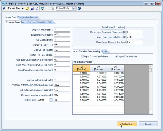
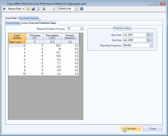
Once the user has successfully input all the required data, as shown in the following two screen captures, they can press the calculate button to calculate all stages of the performance prediction.
The user can choose to enter Relative Permeability table values, as shown below, or choose to enter Corey coefficients for Oil and Water curvature, since all the other endpoint parameters are required for other calculation steps [ kro, krw, Sor, Swc ].
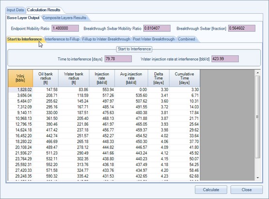
Stage 1 : Start to Interference
The Stage 1 - Start to Interference is calculated if the user input an initial gas saturation value > 0.
Note that all data within the tables can be output to the clipboard by pressing CTRL+C
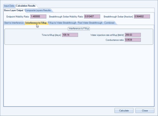
Stage 2 : Interference to Fillup
The Stage 2 - Interference to Fillup is also calculated if the user input an initial gas saturation value > 0.
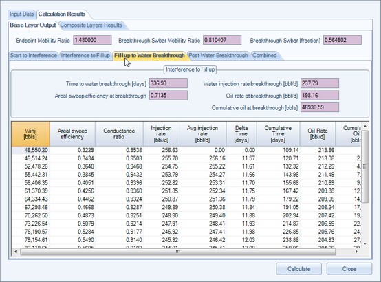
Stage 3 : Fillup to Water Breakthrough
The Stage 3 - Fillup to Water Breakthrough calculation panel is shown below :
Note that all data within the tables can be output to the clipboard by pressing CTRL+C
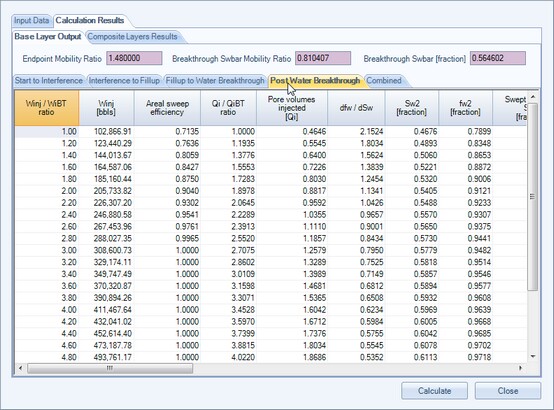
Stage 4 : Post Water Breakthrough
The Stage 4 - Post Water Breakthrough calculation output panel is shown below :
Note that all data within the tables can be output to the clipboard by pressing CTRL+C
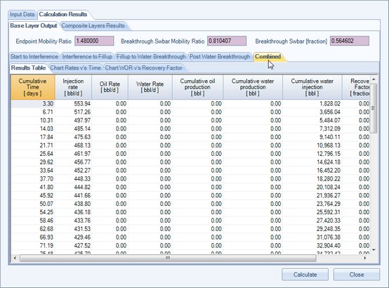
Stage 5 : Combined Base Layer Profile Prediction
The combined base layer performance output panel and charts are shown below :
Note that all data within the tables can be output to the clipboard by pressing CTRL+C
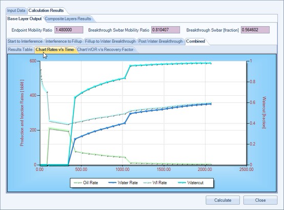
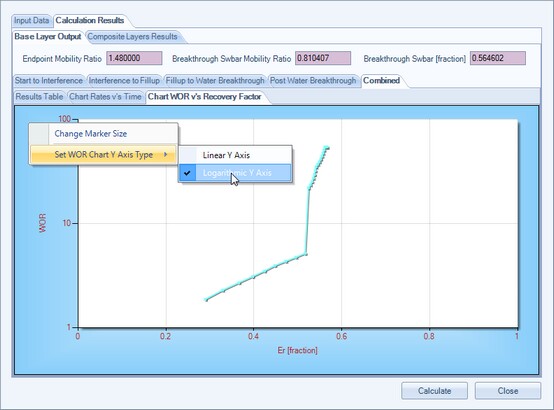
To switch between a Linear Y Axis and a Logarithmic Y Axis on the above WOR v's Er plot, select the chart's context menu by a single right mouse click within the chart area.
Stage 6 : Combined All Layers Profile Prediction
The combined all layers performance output panel and charts are shown below.
Note that all data within the tables can be output to the clipboard by pressing CTRL+C


The user can choose to display the Y axis of the WOR versus recovery factor as a logarithmic scale, in line with common industry practice. To switch between a Linear Y Axis and a Logarithmic Y Axis on the above plot, select the chart's context menu by a single right mouse click within the chart area.
References:
Craig, Jr., F., "The Reservoir Engineering Aspects of Waterflooding", Society of Petroleum Engineers, 1971
Page url: http://www.YOURSERVER.com/help/index.html?example.htm